Roads
There are many types of roads from small secondary country roads to large multi-lane motorways. The main criterion placed on a road is that it should be able to transport people and goods in a safe, rapid, economic and comfortable manner. In order to fulfil this, certain demands are placed on where the roads are built, their surface evenness and surface friction.
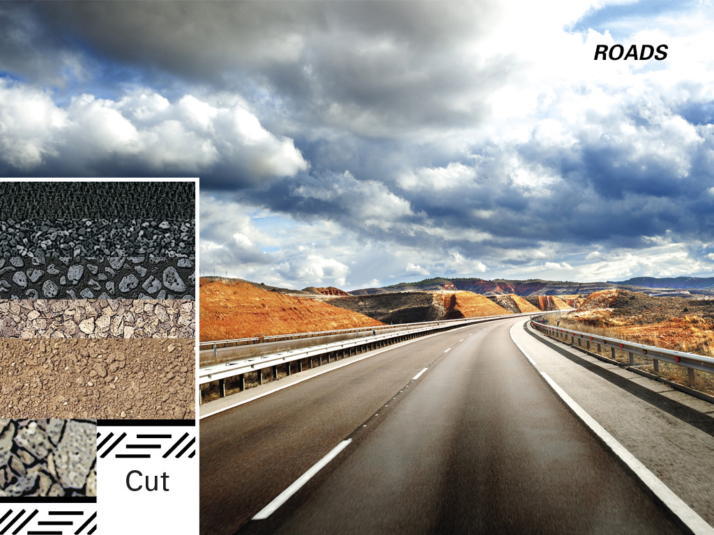
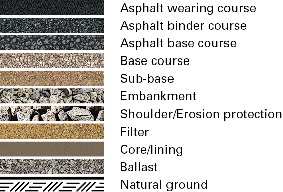
 Layers cross-section
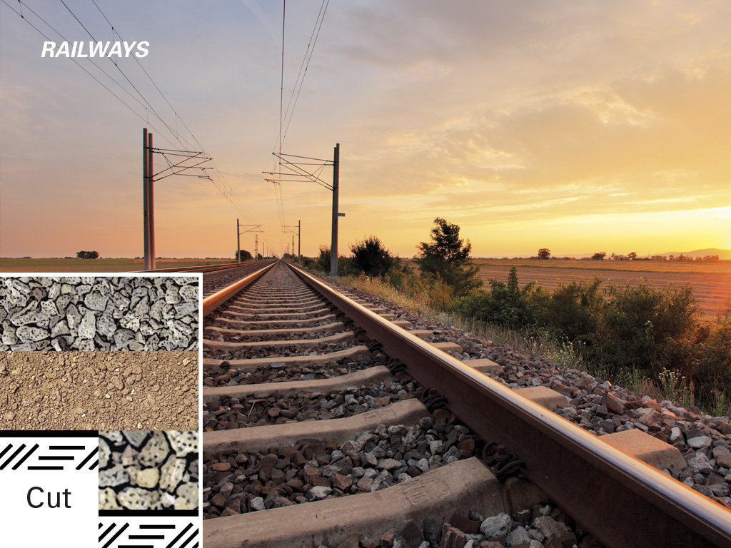
Railways
In many parts of the world railways are still the major form of transport for goods and passengers. The transport of heavy materials such as ore, coal and other minerals places great stress on the railway embankments.
Railways are built according to the same principles as a road except for the bound upper layers. The ballast bed on top serves to keep the sleepers in place. There have also been tests with a bitumen bound top layer to keep the sleepers in place. With the advent of high speed trains in a number of countries, considerably stricter requirements are being imposed on railway embankments and ballast beds.
 Layers cross-section
Airfields
Runways, taxiing areas and aprons are all exposed to heavy loads in airport complexes. They are built up in the same way as roads, but the specifications are more stringent. For example, under no circumstances must the surface break up so that loose stones can get into in the airplane engines.
 Layers cross-section
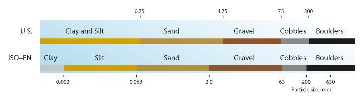
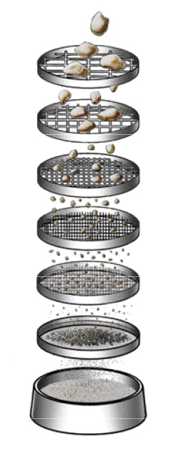
Material requirements
Control methods (selection)
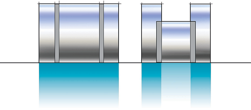
Stiffness
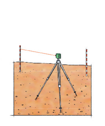
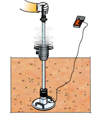
Levelling
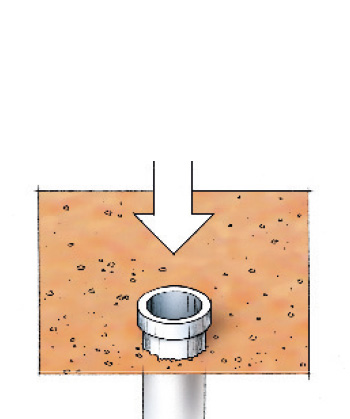
Density
Construction process
A new project typically starts by removing vegetation and organic material from the site. This reveals the sub-grade surface. Adjustment of this surface to the correct level is done by dozers or excavators. The surface is then often compacted using single drum vibratory rollers. Embankment fills are built up in layers that are compacted separately. The closer you get to the finished surface, the higher the demands on both material and compaction results. Sub-grade and base course material face very strict requirements on this. Meeting these requirements is crucial to achieve the expected quality of the design.
Asphalt paving requires proper planning and a good logistics organization. As this is a continuous process it is very important to have a continuous supply of material. The size and the number of pavers and rollers must also be dimensioned with sufficient capacity to avoid unnecessary stops due to insufficient capacity.
Machine selection
Compaction of unbound materials
Paving and compaction of asphalt layers
Continuous operation of paver and rollers is vital to achieve good quality asphalt surfacings. The right number of passes with the correct roller settings is one of the ingredients here. This must be done at the right temperature as well, asphalt cannot be compacted below a certain temperature. The refusal temperature depends on the type of asphalt mix and the binder that is used.
Selecting a proper rolling pattern is even more important than for compaction of unbound materials. Compaction must be completed before the asphalt cools down.
Useful rolling tips:
Drums of equal diameter provide uniform compaction effort across the entire machine width, which conventional three-wheel rollers do not.
- Start rolling at the lowest edge and place the following tracks up the cross slope.
- Switch the vibration off before stopping to change driving direction.
- Drive forward and reverse in the same track.
- Use vibration going both forward and in reverse.
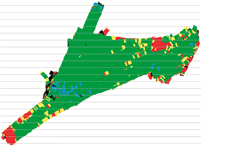
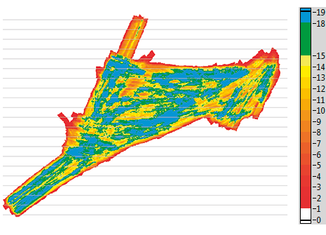
Continuous compaction control (CCC)
Compaction meter and documentation systems
Principle and function
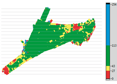
A roller-mounted compaction meter consists of an accelerometer mounted on the vibrating drum. The accelerometer readings are sent to a processor and the readings are presented to the operator on the control panel of the roller. The signals from the accelerometer are converted to values that indicate a relative measure of the stiffness of the ground. The system records conditions at certain depths. The actual depth depends on the size of the roller and amplitude selected. A computer documents and presents the measured values on a screen, which can be placed in view of the roller operator. The documentation system enables the entire area that has been rolled to be presented on the screen. The use of colour and other graphics makes it immediately apparent which areas require additional compaction. A GNSS receiver provides accurate positioning and speed information to the on-board system. The documented result can then be transferred to the office for final analysis and storage.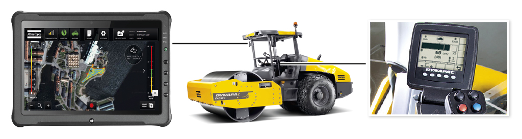
Applications
The compaction meter (with or without the documentation system) is most suitable on coarse-grained soil and rock fills. A soft, uncompacted soil gives little response while a hard, well compacted soil will give a better response. The stiffness increases in proportion to the bearing capacity.
CCC can be used and specified as one or more of the four different methods described below.
Weak area analysis
The CCC values are used to define one or more areas where the soil stiffness is the lowest. These areas are then subjected to directed testing. If the areas pass the test this means the rest of the area is okay.
Calibrated target value
The CCC values are calibrated to create a correlation to the acceptance control method, typically static plate load tests. Using this correlation a corresponding CCC value is determined and used as the target value for the area.
Pass count
Using the CCC system to count and document the number of passes made helps the operator achieve uniform compaction results and provides documentation that the job was done according to the specification.
Progress
The CCC values increase with every compaction pass, a higher increase for the first passes and a lower increase for the later passes. Once the increase from one pass to the next is below a certain level there is very little more compaction to be achieved. This is one measure that can be used to determine when the compaction is finished.